List of Figures
SciDAVis is a user-friendly data analysis and visualization program primarily aimed at high-quality plotting of scientific data. This is the first part of a series of videos demonstrating how to make publication quality scientific figures as part of the NTU Chemistry Professional Pract.


Scidavis Break
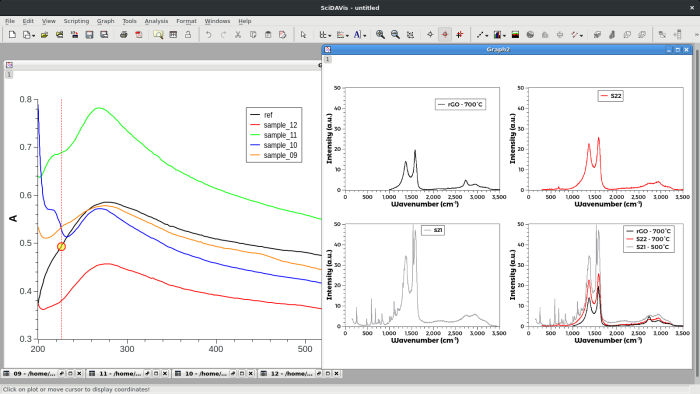
- 1.1. A typical SciDAVis session
- 1.2. A SciDAVis table with the properties dialog developped and the type tag selected.
- 1.3. The two other tags of the properties dialog of SciDAVis tables.
- 1.4. The SciDAVis matrix
- 1.5. An example of SciDAVis 2D graph with 2 layers.
- 1.6. The SciDAVis Note Window
- 1.7. The SciDAVis Note Window used as a calculator
- 1.8. The SciDAVis Log window with the information related to a fit on a curve
- 1.9. The SciDAVis Project Explorer
- 2.1. A simple 2D plot: the table.
- 2.2. A simple 2D plot: the default plot.
- 2.3. A simple 2D plot: the plot finished.
- 2.4. A table with two series of values (X1,Y1) and (X2,Y2).
- 2.5. A 2D plot with two Y and two X axis.
- 2.6. Direct plot of a function.
- 2.7. Direct plot of a parametric function.
- 2.8. Direct plot of a function in polar coordinates.
- 2.9. Function plot: filling of the X column.
- 2.10. Function plot: filling of the Y column.
- 2.11. The Plot details Dialog: general properties of the layers.
- 2.12. The Plot details Dialog: Plot Associations.
- 2.13. The Plot details Dialog: Choice of axes.
- 2.14. The Plot details Dialog: Line formatting.
- 2.15. The Plot details Dialog: Symbol formatting.
- 2.16. The Plot details Dialog: Pattern formatting for bars.
- 2.17. The Plot details Dialog: Spacing formatting for bars.
- 2.18. The preferences dialog: 2D plot options.
- 2.19. An example of pie plot.
- 2.20. Pie segment formatting.
- 2.21. An example of a vector plot (fluid flow around a cylinder in a laminar mode).
- 2.22. Vector-XYXY formatting.
- 2.23. Vector-XYAM formatting.
- 2.24. An example of a box plot for three columns.
- 2.25. The Custom Curves Dialog for box: pattern formatting.
- 2.26. The Custom Curves Dialog for box: whiskers formatting.
- 2.27. The Custom Curves Dialog for box: percentile formatting.
- 2.28. An example of histogram.
- 2.29. Pattern formatting in histograms.
- 2.30. Whiskers formatting in histograms.
- 2.31. Interval selection in histograms.
- 2.32. Example of a 3D Plots.
- 2.33. Definition of a new surface 3D plot
- 2.34. The 3D surface plot created by default
- 2.35. Assigning a multi-lines formula to a matrix
- 2.36. The Contour curves options dialog.
- 2.37. The preferences dialog: 3D plot options.
- 2.38. The text options dialog.
- 3.1. A signal and the FFT dialog box for a plot.
- 3.2. The resulting FFT with the characteristic frequencies.
- 3.3. The FFT dialog box for a table.
- 3.4. Signal after a FFT low pass filter
- 3.5. Signal after a FFT high pass filter
- 3.6. Signal after a FFT band pass filter
- 3.7. Signal after a FFT block band filter
- 3.8. An example of a correlation between two functions: the two signals.
- 3.9. An example of a correlation between two functions: the correlation function.
- 3.10. The first step of the Fit Wizard dialog box.
- 3.11. The second step of the Fit Wizard dialog box.
- 3.12. The results of the Fit Wizard.
- 3.13. The results of a Quick Fit→Fit Linear.
- 3.14. The results of a Quick Fit→Fit Bolzmann (Sigmoïdal).
- 3.15. The results of a Quick Fit→Fit Gaussian.
- 3.16. The results of a Quick Fit→Fit Lorentzian.
- 3.17. The selection of the position of the peaks.
- 3.18. The results of a Quick Fit→Fit Multipeak→Gaussian.
- 3.19. The preference dialog for fitting.
- 3.20. Comparison of the three methods of interpolation
- 5.1. The New→New Function Plot dialog box.
- 5.2. The New→New 3D Surface Plot dialog box.
- 5.3. The New→New 3D Surface Plot dialog box.
- 5.4. The result of Open image File.
- 5.5. The Export Graph→Current dialog.
- 5.6. The basic Print dialog.
- 5.7. The Export Ascii dialog.
- 5.8. The Import Ascii dialog.
- 5.9. The general options dialog: application options.
- 5.10. The plot wizard dialog box.
- 5.11. The project explorer panel.
- 5.12. The undo-redo history.
- 5.13. The scripting console.
- 5.14. The Add/Remove Curve dialog box.
- 5.15. The Add Error Bars dialog.
- 5.16. A plot with X and Y Error Bars.
- 5.17. The Add Function dialog box: cartesian coordinates.
- 5.18. The Add Function dialog box: parametric coordinates.
- 5.19. The Add Function dialog box: polar coordinates.
- 5.20. The Add Text dialog box.
- 5.21. The Arrow options dialog: first tab
- 5.22. The Arrow options dialog: second tab
- 5.23. The Geometry dialog: third tab
- 5.24. The Add Layer dialog box.
- 5.25. The Arrange Layers dialog
- 5.26. The Integrate dialog box.
- 5.27. The Smooth→Savitsky-Golay dialog.
- 5.28. The Smooth→Moving Window Average dialog.
- 5.29. Comparison of the two smoothing methods.
- 5.30. The dialog and an example of FFT smoothing.
- 5.31. 2D plot options dialog: General settings.
- 5.32. Surface plot options: general settings.
- 5.33. Plot options dialog: scales settings.
- 5.34. Surface plot options: scales settings.
- 5.35. General plot options dialog: the axis tab.
- 5.36. General plot options dialog: the grid tab.
- 5.37. Surface plot options dialog: the title tab.
- 6.1. The SciDAVis File Toolbar
- 6.2. The SciDAVis Edit Toolbar
- 6.3. The SciDAVis Plot Toolbar with its different sub-menus
- 6.4. The SciDAVis Graph Toolbar with its different sub-menus
- 6.5. The SciDAVis Table Toolbar
- 6.6. The SciDAVis matrix Plot Toolbar
- 6.7. The SciDAVis 3D Surfaces Toolbar